Electrical Diagnosis How-To
by Vaughan Scott
A complete how-to guide on electrical problem diagnosis for dummies
Electrical problems are one of the most common problems in old cars,
ranging from small annoying items like windshield wipers that seem to have a mind of their
own (or are responding to rain in remote parts of the world!) to major problems like
ignition coils that won't ignite, or fuel pumps that can't put out. Everybody's heard
legends about Lucas electrics. They are also one of the most expensive repairs you can pay
for, since most of the bill will be spent in diagnosis. Very little in the way of
replacement parts are usually required to fix electrical problems, since they are
typically a result of inoperative circuits. However, because of a lack of understanding
and knowledge, most car owners are unwilling or afraid to take on diagnosis of electrical
problems themselves, preferring to shell out hard-earned cash to a mechanic who may not
have much more ability than them to fix the problem!
Yet it is the very nature of electrical faults that makes them just scream
out to be fixed by the novice DIY-er, since little in the way of tools or expertise is
necessary, and the results of a little time spent in some serious diagnosis can be huge,
not just in the problems fixed, but also in the ego boost received! A little bit of time
spent understanding the factory wiring diagrams (as seen either in a Haynes manual or,
even better, the factory manual) and a small investment in a multimeter that will read
both voltage and Ohms, at a minimum, will reap great rewards. You will find yourself no
longer willing to put up with minor oddities in your car, such as a heater fan that only
comes on in one switch position, when you know that a little effort with some sandpaper
will have it working as good as new!
This then is the intent of this article; to uncover the mysteries of the
electrical circuit diagrams to our cars, explain the basic types of circuits used, to
describe how this knowledge can be used to predict how the circuit should function, and
how circuit behaviour observed using the multimeter can be used to isolate the problem(s).
How to read wiring diagrams:
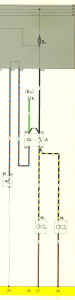
 The
basic wiring diagram is best visualized like the wires hold water (Figure 1). Power flows
from the top, which represents full battery voltage (+12V DC, the positive terminal), to
the bottom, which represents ground (0V DC, the negative battery terminal), and loses
voltage (hence the ability to do work) as it works its way to the bottom of the page, and
when at the bottom is back at ground and unable to do any work. Sure, there are a number
of exceptions to this, such as (most obviously) the battery, but following the current
paths from the top to the bottom is the easiest way to begin to understand the concept of
the layouts and to understand how the circuits are intended to work.
The
basic wiring diagram is best visualized like the wires hold water (Figure 1). Power flows
from the top, which represents full battery voltage (+12V DC, the positive terminal), to
the bottom, which represents ground (0V DC, the negative battery terminal), and loses
voltage (hence the ability to do work) as it works its way to the bottom of the page, and
when at the bottom is back at ground and unable to do any work. Sure, there are a number
of exceptions to this, such as (most obviously) the battery, but following the current
paths from the top to the bottom is the easiest way to begin to understand the concept of
the layouts and to understand how the circuits are intended to work.
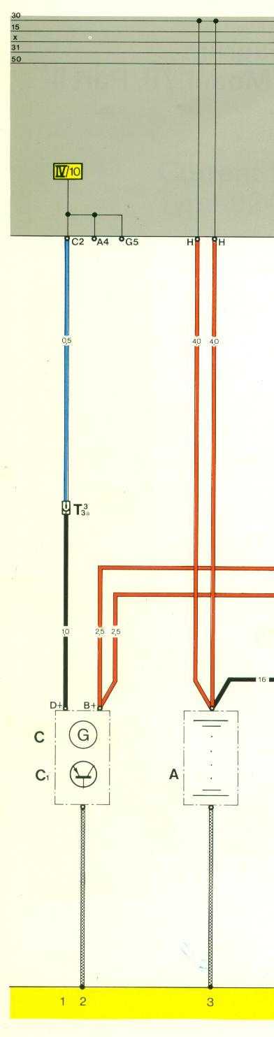
There are, furthermore, some basic identification standards used in
labeling common circuits, understanding which will aid any electrical fault diagnosis. The
standards appear on many German cars, not just Porsches! First of all, circuits connected
to the battery (directly, no switches) are identified as 30. Circuits energized (powered)
when the ignition are switched on are labeled 15. Circuits energized only when the key is
in the crank position are labeled 50 - this is usually just the starter solenoid. Circuits
normally powered in the run position, but deenergized when in the crank position (perfect
example - headlights and radio) are labeled "X". These can all be confirmed by
looking on the wiring diagram for your car at the headlight switch itself; internal
function will usually be depicted as a mechanical "stick" linkage, clearly
showing which contacts are engaged when. These circuit identifications are useful to know
not just because they show up regularly in the wiring diagrams; they are also used on the
actual parts and connectors in the cars, allowing for easy identification of circuits. For
example, a car is easily hotwired by removing the ignition switch plug and jumping between
30 (battery) and 15 (ignition) and touching a lead from 30 to 50 (starter). Since all of
these circuits will be at +12V, they are always shown up at the top of the wiring diagram
for simplicity. Additionally, the wire colour brown is almost invariably used to denote
ground wires.
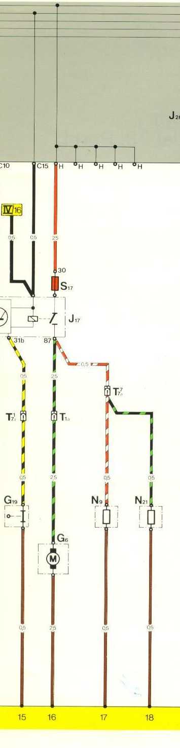
 Armed
with this knowledge, you can begin to understand how the individual circuits, depicted as
a vertical line with components spaced down it, function. Power comes from the top, from a
line labeled 30, 15, or X usually, down through a fuse, perhaps through a relay, through
an item such as a bulb or a motor or through a controlling switch (depending on the
circuit configuration as explained below), then eventually to ground. As can be seen in
Figure 2, power for the motor G6 and the loads N9 and N21 comes down from the top line,
which is circuit 30 (not shown), so battery voltage at all times, down through fuse S17,
is switched on by the relay J17 (only part of which is shown for simplicity), branches
through a couple of connectors (T1a and T7a), through the motor/loads, then down to
ground. This example circuit is actually that for the fuel pump, which explains the
special relay; it has an integrated circuit to detect the correct signal from the
distributor, only switching on when the engine is cranking, as an obvious crash safety
measure.
Armed
with this knowledge, you can begin to understand how the individual circuits, depicted as
a vertical line with components spaced down it, function. Power comes from the top, from a
line labeled 30, 15, or X usually, down through a fuse, perhaps through a relay, through
an item such as a bulb or a motor or through a controlling switch (depending on the
circuit configuration as explained below), then eventually to ground. As can be seen in
Figure 2, power for the motor G6 and the loads N9 and N21 comes down from the top line,
which is circuit 30 (not shown), so battery voltage at all times, down through fuse S17,
is switched on by the relay J17 (only part of which is shown for simplicity), branches
through a couple of connectors (T1a and T7a), through the motor/loads, then down to
ground. This example circuit is actually that for the fuel pump, which explains the
special relay; it has an integrated circuit to detect the correct signal from the
distributor, only switching on when the engine is cranking, as an obvious crash safety
measure.
The only degree of complexity added to this simple plan is when circuits
must be tied together. This is particularly true when circuits jump across pages of the
wiring diagrams, as perspective on which way current flows can be difficult. There are
also examples when current flow is bottom to top, such as connecting the starter to the
ignition coil (for a hotter spark when cranking), that can lend confusion. In these cases
the entire circuit must be traced to ensure understanding of the correct current paths.
How circuits are controlled:
Excepting any circuits that are switched only by the ignition switch (such
as the cold start relay and warm-up regulator, the loads in the above example Figure 2),
most circuits will be operated by some form of a switch. This can be either manually
operated by the driver or automatically by a sensor or other arrangement. Furthermore, a
relay may be introduced into the system, in order to provide more power than a
conventional switch could handle. Thus the horn is switched by a relay. In order to
diagnose a problem with a circuit, you must first understand how the circuit should work;
then you can determine why it doesn't work.
Let's start with the simplest case, a taillight. In this case power goes
to a switch (the main headlight switch), then back to the taillight bulb by way of a fuse,
a few connectors, through the bulb, and to ground. If any one of these components are not
working right, you will lose a taillight. Now since the taillights are not switched with
ignition (they can be turned on without the key in), we know that power (+12V DC) goes
from the battery to the switch, through the correct fuse, then out to the taillights. In
this case the switch is operating in the hot side of the circuit; if it is not working, or
if it is off, no power will be applied to the bulb. The bulb is always grounded (unless
contacts are corroded, of course), and will light up at any time that it gets power.
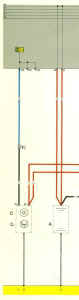
 Let's
take a look now at another possibility, the fans for the radiator. These, as everybody
knows, are switched by a temperature switch whenever the radiator gets hot enough. On cars
with factory AC, it/they can also be turned on by turning on the AC, but we will look at
the basic, non-AC car. So how does it work? In this case (Figure 3), power from the
battery is always available to the fan (through the resistor N39, connected to circuit 30
through fuse S15) so that it can run even when the car is turned off. However, because of
the resistor in the circuit, once power is drawn by the motor, the voltage will be less
than full battery voltage, causing the fan to run more slowly. This is what will allow the
fan to turn on even when the car is parked. In early 924's, this resistor was located
above the radiator and corroded away; later cars (probably 78-onward) have it safely
located behind the dash on the firewall.
Let's
take a look now at another possibility, the fans for the radiator. These, as everybody
knows, are switched by a temperature switch whenever the radiator gets hot enough. On cars
with factory AC, it/they can also be turned on by turning on the AC, but we will look at
the basic, non-AC car. So how does it work? In this case (Figure 3), power from the
battery is always available to the fan (through the resistor N39, connected to circuit 30
through fuse S15) so that it can run even when the car is turned off. However, because of
the resistor in the circuit, once power is drawn by the motor, the voltage will be less
than full battery voltage, causing the fan to run more slowly. This is what will allow the
fan to turn on even when the car is parked. In early 924's, this resistor was located
above the radiator and corroded away; later cars (probably 78-onward) have it safely
located behind the dash on the firewall.
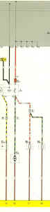
There is also a relay J26, drawing power from circuit 30 through fuse S18,
but only turned on with circuit 15 (ignition). This will supply full power to the fan
whenever the ignition is on - the normal mode of operation.
Once we get past the power source - relay or resistor - this circuit takes
a very different turn (as compared to previous examples). Power goes directly to the fan(s)
(V17 in this example). After the fan(s), it goes to the temp switch F18 (installed in the
side of the radiator), then to ground. As a result, diagnostic attempts on this circuit
will yield rather different results than the taillight circuit. The taillight bulb should
be grounded all the time. The rad fan, however, will not be grounded until the radiator is
hot enough! Therefore you must test for a ground at the temp switch, not at the fan. At
the fan you should be looking for power, and continuity (0 Ohms resistance) to the temp
switch. If you short out the terminals of the temp switch at any time, the fans should
turn - if they work, of course!
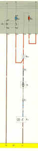
 One
last example, a variation on the above theme, as a comparison; this one, the horn circuit.
As before, we have the arrangement of power going, in turn, to the fuse, relay, horns, and
ground. The main difference here is in the switching for the relay; whereas the above
circuit is switched by ignition, this circuit is switched by the horn switch (H, on the
steering wheel). The relay is turned on using a ground switch just like the temp sensor;
in this case, power goes through the control circuit on the relay, through a wire to a
contact on the steering wheel and up to the horn pad (Figure 4). When you press on the
horn pad, the wire is grounded to the steering column, completing the circuit, turning on
the relay, and providing power to the horns.
One
last example, a variation on the above theme, as a comparison; this one, the horn circuit.
As before, we have the arrangement of power going, in turn, to the fuse, relay, horns, and
ground. The main difference here is in the switching for the relay; whereas the above
circuit is switched by ignition, this circuit is switched by the horn switch (H, on the
steering wheel). The relay is turned on using a ground switch just like the temp sensor;
in this case, power goes through the control circuit on the relay, through a wire to a
contact on the steering wheel and up to the horn pad (Figure 4). When you press on the
horn pad, the wire is grounded to the steering column, completing the circuit, turning on
the relay, and providing power to the horns.
Now you can see why so many electrical problems arise in these cars when
grounds are not in good shape; switching of all the circuits is completely dependent on
having good grounds!
Diagnosis Begins: Check the fuses
Naturally the first step that should be undertaken when diagnosing an
electrical problem is to check the cheap, simple stupid stuff. Make sure the fuse is good;
the fuse should be able to be identified from the owner's manual or from the wiring
diagram in a repair manual. There are a few cases where fuses are not located in the
normal locations on the relay board, such as some fuel pump relays. These may have to be
located through tracing wires! Likewise don't forget to check bulb filaments, in the case
of lighting circuits. Furthermore, when checking fuses and bulbs, the contacts must also
be checked. Bulbs can often be subjected to substantial corrosion, which can be cleaned
off easily with fine sandpaper. Bullet-style fuses can often be subjected to corrosion
that is less obvious, but impedes current flow nonetheless; it just looks like a little
varnish. Replacing the fuses is the best bet on an old car, since they can fail with age
at an inoportune time, and sand the contacts on all fuse locations in the fusebox as a
matter of course.
Completing the circuit: Checking grounds
The next easiest diagnosis step in the process, and keeping in tune with
our effort to fix the problem cheaply, is to check the grounds. When getting a
"new" used car, it is often wise to systematically go through and clean all
grounds anyway, since they are usually bad. Grounds in a car are identified in the body
section of the factory manuals; in the 924/944, there are grounds as follows: behind each
headlight to the body frame rail, at the coil mounting on the firewall (main grounding
point for the motor), in the battery (grounding point for the battery), under the dash
behind the fusebox on the firewall (main grounding point for body/internal dash
electrics), and by the taillights under the carpet in the rear hatch. These should all be
disconnected, wire brushed till clean, and reassembled. For the bolt-in type of grounds, a
new star washer would be best to ensure good metal-to-metal contact.
When troubleshooting a specific circuit, ground must still be checked even
if the above steps of cleaning the grounds have been taken. This is where the multimeter
shows its superiority over a test light. Use the wiring diagram to determine the last
point in the circuit before ground. Use the ohmmeter function on the multimeter to check
for continuity (0 resistance) between this point and the ground location. In the
taillights, for example, the base plate of the light housing which the bulbs are inserted
into forms a common ground for the bulbs, and you should be testing for continuity between
this and your ground. The lead from this, which will be brown as previouly noted, should
show 0 Ohms resistance to your grounding point. If it does not, inspect the wire and any
connectors (a 7-pin nylon connector to the taillight housing, in the case of the
taillights) for any breakage or damage, or any corrosion at connection points.
Naturally, in the case of a circuit with multiple grounds, ground may need
to be checked at different locations. For example, if the horn is not working but has a
good ground, it is possible that the horn switch is not grounding, preventing the relay
from operating and powering up the horn. This is where the wiring diagram again comes in
handy, since it will describe how the circuit works.
Bulb Check: Looking for the power source
Now, and only now, do we get to the point where we try to find out if the
item which is not working is getting power. The reason for this is because you want to
start with the most likely causes first! It is more commont for a fuse or ground point to
be corroded or otherwise broken or damaged than it is for the part to not be getting
power. There are a few small exceptions to this - such as headlight motor or starter - so
the best general diagnosis technique is, as shown above, check the fuses and ground first.
Start at the part, be it taillight or fan motor or whatever, turn on any
relevant switches necessary to turn that part on, and check for power on one of the
contacts leading to that part using the voltmeter. Naturally, you should read full battery
voltage on the connector; put the voltmeter across the battery terminals to compare. If
voltage is present but lower than battery voltage, there is a poor circuit, possibly with
some corrosion or damaged wires between the battery and where you're checking, and this
will need to be fixed. If there is no voltage showing at all, the causes will be either
that there is, again, a broken, corroded, or damaged wire or connector, or a switch or
relay "upstream" is not working.
The quickest way to isolate the location of the problem is to continue to
work your way upstream through the wiring diagram, working your way back until you find
full battery voltage. Check for power at connectors, switches, relays, etc., until you
find full battery voltage. It is then apparent that the next section of wiring is the
problem and must be physically inspected, looking for corrosion and for damage to the wire
insulation, possibly cracking or burnt insulation. If corrosion is found, it can be
cleaned off with a wire brush or sandpaper and WD40. If damage has occurred to the
insulation or wire itself, the damaged section of wire must be replaced. See notes at the
end about repairs to wiring.
But how do you tell if a switch or relay is bad? Use the multimeter and
the wiring diagram! Use the multimeter to check for continuity between the terminals on
the switch that you've identified in the wiring diagram that correspond to the circuit
you're having a problem with. This most likely will be using the wire color codes noted in
the wiring diagram. If you do not detect continuity, then the switch is clearly bad, and
must either be repaired or replaced; it is sometimes possible to disassemble the switches
and remove internal corrosion, or repair internal wire breaks with soldering, and then
reassemble and reuse the switch.
With the relay, checking is a little more difficult. The simplest thing to
do is to see if the relay "clicks" when switched - by putting your hand on it
and see if you can feel the motion from it engaging when you hit the switch to actuate
that circuit, like pushing on the horn button. If this does not work, most likely the
relay is dead; try replacing the relay itself with a short piece of wire with male spade
connectors crimped on and see if the affected part now has power. If it does then, chances
are good that the relay is bad. However, be aware that there are a few more complex
relays, such as fuel pump relays, that have more complex internals, and so they cannot be
tested so easily. For the fuel pump relay, a signal from the distributor is expected. For
these reasons, some more complicated relays can only be completely tested by replacement.
However, replacing it with a jumper will easily allow you to isolate if the problem lies
in the relay, or possibly it's switching circuit, as opposed to the main power supply for
the affected part.
That being said, switching circuits for a relay (the circuit that turns
the relay on and allows power through it) can be trouble-shot just like any other circuit,
using the same rules; look for grounds, look for power, and look for damaged wiring.
What if you find power at the part when you start your diagnosis, and
you've already determined that you've got a good ground? Then either you have a corroded
connector, or you have a broken part! Finally, you can think about replacing the part.
You've made sure it's getting power when it should, and you've made sure it has a good
ground path to use. Unless there is corrosion on the connector, or unless there is further
internal wiring within the component (such as a relay or other internal connections on a
windshield wiper or headlight motor), the part is likely bad. One more possibility for the
connector to be bad; over time, the tight fit of a metal connector may become relaxed,
preventing it from contacting all the time. Easy to diagnose - wiggle the connector!
Headlight motors on 924/944's often suffer from this or a bad relay. If neither of these
produce results, you may have to try swapping the part; hopefully you either have or can
gain access to a spare to borrow for diagnosis. Nothing worse than replacing a whole motor
when a connector is rusty. That's why this step is last - because it's the most expensive!
One final note; another mode of diagnosis of parts can be used, if you're
willing to get fancy, which is individual testing of the component out of the car. This
requires a bit of knowledge on your part about how the part is supposed to work.
Lightbulbs and motors - pretty easy, apply 12VDC and see if they light up or move. Others
you might be able to check the resistance on, looking for an open circuit (no resistance
shown) or short circuit (0 Ohms). This would be more useful for things that don't
apparently "do" anything when working, like a control pressure regulator for a
CIS system. Again, you have to understand what the component does.
Tieing it all together: Circuit interconnections
OK, maybe it's not the last, but this step, while cheap, can be one of the
most difficult and challenging to check! Therefore we leave it last here, as it can be
disheartening if tackled without a plan. This is when various bits and parts of a circuit
are not "talking to" eachother - interconnections are lost, but it's not a
simple straightforward power-switch-accessory-ground circuit like those we've gone through
above. This is where the wiring diagram is key, as it's the only map through those
circuits. In this case, you have to systematically check each portion of the circuit,
ruling out any and all parts of the wiring as possible sources of problems. For example,
you may have to, in a CIS car, check to ensure that one of the wires going to the
thermo-time switch goes to the cold-start valve, requiring you to unplug both parts. The
wiring diagram will show where this interconnection can be checked.
Repairs
Some final notes on repairs to wiring and connectors, as opposed to
replacing components that plug into the wiring harness. This is often necessary due to
heat scorching wires, corrosion causing excessive current draw to melt wires from the
inside out, cracked insulation from age, damage from oil or other fluids, wires frayed on
other parts of the car due to poor mounting, routing, or restraint, and the like.
Connector elements (pins, spades, etc) can get bent, corroded beyond repair, broken off,
lose their tight fit, etc.
The most critical thing to remember when replacing wires or connectors is
that great care must be taken to ensure that the repair is not creating opportunity for
new corrosion or other damage! Otherwise you are merely postponing the return of a
problem, instead of fixing a problem. Factory connectors and wiring are done with
attention paid to minimize risks of corrosion. Repairs should be held to a similar
standard. Obviously twisting wires together and wrapping in electrical tape is not
sufficient.
Ideal is to splice in lengths of wire by soldering, and covering with
shrink-tube insulation, unless an entire section of wire can be replaced from connector to
connector without splice. A paint-on sort of electrical insulation can also be found, and
is excellent also at sealing against moisture. Often replacement connector pins can be
found at electronic and electrical supply places, look in the yellow pages. Make sure you
have the correct crimping tools, as well. No-solder crimp-only type connectors are not
preferred; at least solder those connectors after crimping to ensure longevity. Think
about how moisture can enter the wiring, and take pains to ensure those paths of intrusion
are sealed as well as possible.
As mentioned, damage to wiring can also take place because of where the
wire is routed; when repairing wiring, make sure that wire is routed well away from any
heat sources, is properly secured with tie wraps, is protected from rubbing on any metal
that could cut through, and is never under any tension - cut wires longer than necessary,
or splice in additional wire.
Any electrical issue found in our cars can be isolated, diagnosed, and
repaired with a good basic understanding of how the electrical systems work, how they're
depicted in the wiring diagrams, and how to check each part and type of circuit found in
the car. A great deal of labor costs can be saved through some time "bonding"
with the car, tracing circuits, and a lot of small, annoying, trivial inconveniences can
be fixed permanently through some basic preventative measures. All of which means more
time, money, and confidence to take your toy out and enjoy it the way it was meant to be -
on the open road!
 The
basic wiring diagram is best visualized like the wires hold water (Figure 1). Power flows
from the top, which represents full battery voltage (+12V DC, the positive terminal), to
the bottom, which represents ground (0V DC, the negative battery terminal), and loses
voltage (hence the ability to do work) as it works its way to the bottom of the page, and
when at the bottom is back at ground and unable to do any work. Sure, there are a number
of exceptions to this, such as (most obviously) the battery, but following the current
paths from the top to the bottom is the easiest way to begin to understand the concept of
the layouts and to understand how the circuits are intended to work.
The
basic wiring diagram is best visualized like the wires hold water (Figure 1). Power flows
from the top, which represents full battery voltage (+12V DC, the positive terminal), to
the bottom, which represents ground (0V DC, the negative battery terminal), and loses
voltage (hence the ability to do work) as it works its way to the bottom of the page, and
when at the bottom is back at ground and unable to do any work. Sure, there are a number
of exceptions to this, such as (most obviously) the battery, but following the current
paths from the top to the bottom is the easiest way to begin to understand the concept of
the layouts and to understand how the circuits are intended to work.