
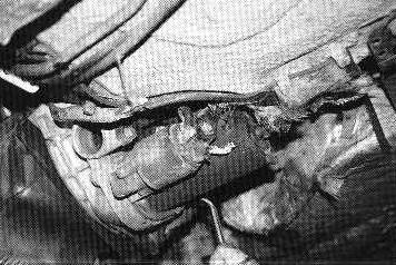
Clutch replacement is a big job! Transaxle with disconnected wiring and axleshafts is ready to be unbolted for removal
TECH FORUM
by Jim Pasha, EXCELLENCE - October 1999
924/944/968
Clutch Replacement
Recently, I have received a large amount of mail from 924 and 944 owners regarding clutch problems. Anything from a slipping clutch or a failed throw-out bearing to a failed rubber center or a burned clutch disc can ruin the driving pleasure of your Porsche. Clutch replacement is often seen as a repair that is outside of the capabilities of a home mechanic, but this just isn't so. It is, however, a major repair. Even if you do not wish to take it on yourself, knowing what the job entails may help you make better decisions when consulting your Porsche mechanic.
Porsche's rubber-centered clutch discs were used in the 914 2.0, the 911 from the mid-seventies until 1989, and the 944/924S/944S/944S2 models. The rubber is subject to material breakdown due to age, usage, and oil or fuel contamination. Despite the heavy criticism this clutch design has weathered, it is an important part of the drivetrain. The rubber center is designed to absorb the shock transmitted when the clutch is engaged or disengaged and the stress resulting from getting on and off the throttle. The rubber center accomplishes this dampening action better than spring-centered discs.
Clutch replacement is a big job! Transaxle with disconnected wiring and axleshafts
is ready to be unbolted for removal
I recently purchased a 1987 924S with a failed clutch disc. I opted to hire a good shop to replace the bad components, but will describe the process here. It is entirely possible to do the clutch replacement in your garage at home. Clutch replacement on a 924 usually takes about 7.5 hours. A 944 will require about 9.5 hours. The 944 Turbo will require 14 hours. The 944 Turbo takes longer because the turbocharger's crossover pipe and wastegate must be removed and the exhaust system is much more complex. All of these time estimates assume that nothing is broken and that no bolts are stripped.
What Clutch to Buy
I recommend Sachs components because they have supplied Porsche OEM components for many
decades. I consulted Sachs and selected a rubber-centered replacement kit for my 924S,
which shares its drivetrain with the 2.5 liter 944. There is also a spring-centered clutch
disc kit available. If your car is used on the track for driver's education or Porsche
Club of America competitive events, I highly recommend the spring-centered clutch because
it is better for track use.
For a car that rarely sees the track, use the rubber-centered disc kit. Sachs also lists other pieces that are necessary for a clutch job, such as pilot bearings and pilot shafts. the pilot bearing is a necessary piece that should be replaced whenever you service the clutch. The pilot shaft is required to align the clutch disc during assembly to allow proper alignment of the driveshaft. Prices for the clutch kits are reasonable - usually under $400. Shops do charge more for the components, but this is part of their profit so shop around when getting quotes if you decide to have a shop do the work.
The Big Job
Replacing the clutch assembly in your 924/944/968 is a big job if you do it at
home. You will have to remove the following: exhaust system, transaxle, ignition sensors,
driveshaft, clutch slave, starter, bellhousing, and the clutch components themselves.
For this job, you will need at least 18 inches of room between the ground and the bottom of the car. This will require a pair of good jack stands at both ends of the car. Make sure the car is securely resting on them before getting underneath it.
The first order of business is to disconnect the negative battery lead because you will be disconnecting the starter. The hot lead carries enough current to cause serious injury. Make sure you have the security code for your radio and/or alarm before you disconnect the battery.
Next, locate the ignition sensors just behind the head on top of the bellhousing. These are held in place by allen cap screws. Unfasten the screws and gently pull the sensors out of the aluminum frame. This will allow you to avoid having to reset the depth during reassembly. Note that there is a ground strap to the bellhousing on the 1985.5-and-later models, which will be removed later.

Go to the underside of the car. The exhaust system must be removed. I usually unbolt the system at the engine exhaust manifold flange and then drop the entire system. If you like, you can break the manifold in the middle at the center flange and take it out in two pieces. Note that there are two hangers on the driveshaft. At this time, loosen the U-bolts that hold these hangers, but do not remove them.
Next, go to the inside of the car, pull back the shifter boot, and remove the clip that holds the knob in place. Remove the knob. Pull the circlip that holds the shifter rod on the shift lever, then remove the rod. The next step is to separate the foam at the 12 o'clock and 6 o'clock positions and remove the bolts holding the shifter lever base. Remove the shift lever.
Now you can go to the rear of the car and start removing the transaxle. Disconnect the reverse switch wiring., then the electronic speed sensor - if your car is so equipped. Using a new allen socket or a 12-point socket in very good condition, loosen and remove the CV-joint bolts from the transaxle end of the axleshafts.
Disconnect the shift rod from the cup receptacle on the transaxle cross-shaft. This has a safety wire on the bolt and should be rewired during the reassembly process, so note the direction of the wire on the bolt and how it is twisted. There is an access panel to the driveshaft adapter. Remove the panel and using a light to illuminate the area, loosen the two allen bolts on the coupling collar. The driveshaft must be rotated to reach both bolts. When loosened, slide the collar back onto the transaxle input shaft.
The next procedure is a bit tricky and must be followed in sequence. Support the transaxle with a jack. The pictures show a built-for-purpose transmission jack with chains to hold the transaxle. Position the jack under the ring-and-pinion area of the transaxle and raise the jack to the point where it takes some pressure off of the transaxle mounts.
Remove the bolts that hold the mount to the floor of the luggage compartment. This is actually a welded member of the chassis. Once the bolts are removed, lower the jack slightly - but not too much. Now remove the bolts from the transaxle bellhousing and the driveshaft adapter. There is not a lot of room behind the transaxle to move it away from the driveshaft. Lower the transaxle slightly to break the bond, then remove the plastic tube that the shift rod passes through at the transaxle bellhousing. As this transaxle was originally designed for a front-wheel-drive car, the shift linkage has to pass through a hole in the bellhousing to reach the shift cross-shaft. The plastic keeps dirt and grunge from getting into the bellhousing area.
The transaxle must come straight down on its way out. The chains on the transaxle jack are to keep the freed transaxle from slipping off of the jack. The transaxle can sometimes hang up on the plastic tube, which will prevent it from being dropped straight down. Some fiddling should allow you to get it free. Once this is done, the transaxle can be dropped down and pulled out from under the car. Do not drop the driveshaft in any of these steps. Lower it gently and let it rest on the torsion-bar tube.
Starter mounted low on the bellhousing - a vulnerable position.
You can now go forward and perform the removal of the starter and clutch-slave cylinder. Do not break the connection to the slave cylinder; unbolt it from the clutch bellhousing and push it forward and out of the way. The starter is at the bottom of the bellhousing and must be removed. In the pictures, we let it dangle from the harness. It would be better to support it.

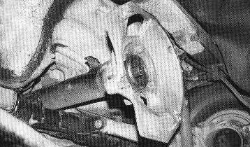
Bellhousing with the starter and clutch slave cylinder removed.
The driveshaft must be pulled back to remove the bellhousing.
The four bolts on the driveshaft can now be removed. You may need to use a long socket extension to get to the top two bolts. Our mechanic had a curved wrench, which looped around the driveshaft, making the job much easier. I usually use the long extension method with a swivel socket. Once the bolts are removed, you can slide the driveshaft back. Remember to leave the hangers for the exhaust system loose. Also note that the driveshaft has two large tangs at the rear that engage the torsion-bar tube. The tangs help to absorb a hard rear shock in the event of an accident. They can and will get in the way.
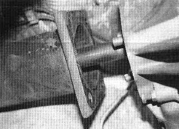
Driveshaft being withdrawn from the bellhousing.
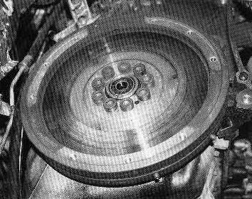
Note flywheel's bolts in the center and the pilot bearing installed.
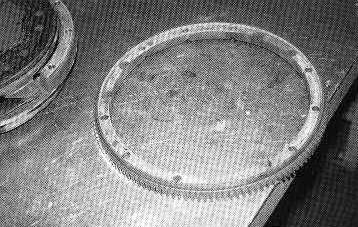
The starter ring gear removed from the clutch pressure plate.
The shaft can be wiggled out by moving the hangers forward or back. The shaft may have to be lifted to clear the tangs. The engine can be raised from the rear to assist in this. The shaft should come back at least one foot from the back of the bellhousing. It will also rotate due to the mass of the flange at the rear. You may need assistance to move the shaft if you are not using a lift. One person can hold and pull the rear while the other moves hangers and supports the forward part of the shaft.
With the driveshaft retracted, you are now ready for the most challenging part of the job. First, remove the clamps holding the wiring harness to the bellhousing. Next, the forward steel dust cover must be removed. After that, remove the clutch release-arm shaft. This may seem unusual, but with the bellhousing in place, it is much easier to use a slide-hammer to remove the shaft. The shaft is threaded internally to allow a slide hammer to be used. It took maybe four good whacks to remove the shaft on this job. The shaft had no evidence of galling when we removed it, so we put it aside to be reinstalled.
Now come the hard part. There are six bolts that hold the bellhousing to the engine block. The lower four can be accessed fairly easily. The top two bolts are hoard because of the limited access near the firewall. With a screwjack, we raised the front of the engine to get enough elbow room to allow a socket and breaker bar to reach up there. The upper bolt on the passenger's side of the engine generally comes out with a little work. The drive's side bolt, however, is always a real pain.
On the driver's side bolt, patience is the key, as simply jerking on it and using brute force will break it off in the engine block. Not a good thing. On this job, the mechanic got it maybe four turns before it started to seize. A few good German curse words, a coating of liquid wrench, and some other mechanical elixirs plus about 20 minutes got the bolt to come out without breaking. this will build character if you car has never been apart before. Mine hadn't.
The bolt should be worked out a little ways, then back and forth in cycles to break it free. Do not force the bolt or it will break or strip the threads in the engine block. Some heat on the block may be applied. I use a small propane torch to do this, but be very careful as there is wiring nearby. Once the last bolt is removed, the bellhousing can be pried loose from the two alignment pins in the block and pulled out. the release arm was loose, so we went slowly so as not to drop it.
Removal of the pressure plate, clutch disc, and release bearing is fairly easy. Remove the mounting bolts by going across the pressure plate in order, loosening each one little by little. By doing this, the spring pressure exerted is relieved evenly. Then remove every other bolt until the pressure plate is free. Be sure to hold the pressure plate to prevent it from falling on you.
You should now be able to see the flywheel and the pilot bearing. Inspect the flywheel for heat checking, cracks or other damage. If there are any signs of checking or heat damage, replace the flywheel. I have only seen one that was bad enough to require replacement for this reason. If there are gouges from a clutch disc surface failure, replace the flywheel. Warping is easy to spot. If you find any warping, replace the flywheel.
If there is just normal wear and no bad grooving on the flywheel's surface, I do not recommend going to the trouble of resurfacing the flywheel. Why not? Modern clutch materials are asbestos-free and require a smooth surface. Unless you can accurately grind the flywheel and prepare the surface on a Blanchard-type grinder, you are better off leaving the flywheel alone. These materials need the factory's finer surface to do their work. An ordinary lathe cannot reproduce this surface.
The start/timing ring gear must be tapped gently to free it from the old clutch pressure plate. The pilot bearing must able pulled to allow the installation of its replacement. The pilot bearing is for driveshaft alignment to the centerline of the crankshaft. this means the clutch is held in tight alignment with the centerline and remains balanced as it spins. Removal of the pilot bearing can be accomplished with a slide hammer that has inside fingers to catch the race while you tap to remove it. The best reason to replace the bearing now is to avoid doing all of this work to replace the bearing if it fails before the next clutch job.
Before installing the new pilot bearing, slide it onto the end of the driveshaft that goes into it when everything is assembled. Make sure that the pilot bearing slides on and off easily. If there is a bind, the driveshaft will continue to turn even when the clutch is depressed. This can happen, especially if the heater valve has leaked fluid into the clutch assembly.
Inspect the old clutch disc. If it had been clunking due to failure of the rubber center, you will be able to easily turn the spline section from stop to stop. When it hits the stop, the section will make a clunk, either as you accelerate or decelerate.
The bellhousing should be cleaned inside and out. Note that there is a steel tube attached to the rear part of the housing. The driveshaft passes through this tube and into the clutch. This tube guides the release bearing and keeps it aligned as it moves in and out during clutch actuation. Over time, this tube will get a worn area from the movement of the release bearing. It is cheap, so replace it. If the wear gets to a point that the release bearing hangs up, you have to go all the way back in to replace it - not a pleasant job for a $10 part.
The release lever has a pair of needle bearings in each leg. These must be replaced. Even if the release arm shaft isn't worn, the original lubricant will certainly be gone. this is not an expensive replacement - just press the old ones out and press the new one in. the release arm and shaft can be reinstalled with the bellhousing still out of the car. Which I recommend doing.
If you have a 924 wit the cable system, the release lever is mounted in bushings. It still requires lubrication and inspection. both styles of release levers have a surface that engages the release bearing. There should be a slight arc to those surfaces. If there is not, the release lever should be replaced. Without that arc, the release bearing suffers from preloading and cocks to an angle when actuated. This makes the bearing hang on the release bearing tube, seriously increasing the required pedal pressure.
Before you do any further work, select the correct thread chaser and carefully run it down each of the bolt bores for the bellhousing bolts on the back of the block. this removes any debris and will help prevent thread crossing or stripping.
Next, take the starter gear and install it on the pressure plate. Note that there are some little points just to the rear of the ring. Care must be taken to avoid damaging the points because they are used by the engine's ignition and timing sensors. Use a pair of bolts to align the ring gear onto the shoulder of the pressure plate. Make sure all holes are aligned.
If you have removed the flywheel to install a new rear main seal or replace the flywheel, always use new flywheel bolts. Though they add to the cost of the project, new bolts are not stretched from being previously torqued. If you are installing a new flywheel and clutch, it would be a good idea to take them to a shop that balances flywheels and engine parts and have the pressure plate, clutch disc, and flywheel matched. This will make things a lot smoother.
Do not lighten a 944 flywheel, however, as the engine depends on the mass to help dampen the crankshaft. The flywheel's mass does as much to balance the engine as the balance shafts do. I would only reduce the weight of the 944 flywheel for racing cars that are never used on the street.
Now it's time to install the new clutch disc and pressure plate. To accomplish this, you will need an alignment tool. There are two types of tools - one has splines matching the clutch disc and the other is round and fits tightly against the inside splines of the disc. The tool has an end that matches the pilot bearing's inner diameter. Try it in the pilot bearing first. If it does not fir, check the diameter against the driveshaft end. If it is incorrect, stop your repair and get the right one. Sachs has the correct one listed next to the clutch kit or under the component listing for your model of Porsche.
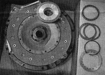
Sachs clutch replacement kit with all new components required, except for the
clutch release arm bearings and release bearing collar.
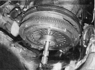
Installing the clutch disc and pressure plate as an assembly.
The next step will be a bit tricky. Take the clutch disc and insert the alignment tool through it. Put the end that goes in the other pilot bearing into the bearing with the disc on it. Next, take the pressure plate and a few bolts and carefully align the pressure plate with the bolt holes and install three bolts to a point where the threads are engaged about three turns. Install the remainder of the bolts to the same pint. Turn the installation tool to make sure it is still engaged in the pilot bearing correctly. Cross tighten the bolts until partially tight. Make sure the clutch disc is still in place by wiggling the alignment tool a bit. Tighten and torque per Porsche's Technical Specification figures for your car's year and model. Haynes has the correct information as does the Porsche Factory Service Manual.
You are now ready to begin the reassembly process. When re-installing the bellhousing, put anti-seize compound on the bolts. This will keep the bolts from freezing in the future. Be sure to torque the bellhousing bolts to the factory specified setting.
You will need to rotate the driveshaft back into position and then slide it forward. When working in your garage without the benefit of a lift, this is really a two-person job. The driveshaft itself will need rotation, as you slide the housing forward to align it with the clutch disc splines. Do not force the driveshaft back into place. It is far better (and less expensive) to disassemble things and find the problem rather than break something. Generally, if you have used the correct alignment tool, the driveshaft will go right in and fit into the pilot bearing. there are alignment pins on the backside of the bellhousing that must be engaged carefully. Do not bend these.
When the driveshaft is in place, replace the starter and clutch slave cylinder. I generally try the clutch at this point to make sure the release arm is actuating correctly and then flush the hydraulic lines and perform a proper brake bleed. 924 owners have a cable-actuated clutch that will need to have the play adjusted. For the 924, wait until the transaxle is reinstalled to adjust the clutch.
Inspect the power cables to the starter and make sure they have been placed correctly. Make sure the ground strap to the upper right bellhousing bolt is replaced. If you have completely removed the ignition sensors, make sure that you have correctly connected them and that the spring clip has engaged to lock them to the support bracket. If you get sloppy, the engine will stop running when the connection is broken. Just don't ask me how I know...
On the exhaust hangers, I find it easiest to re-hang the exhaust system by aligning the hangers to the pipe mounts and then snugging the nuts. I usually wait until after I have the car almost completely together, then I start the engine and let it run for a minute or two while the car is still on jack stands. Then, I tighten the U-bolts nuts and hanger bolts. Starting and running the engine will put the exhaust hangers into position a bit better to keep the system from resonating later.
If any parts of the shifter rod or mechanism need to be replaced, the best time to do this is while the driveshaft is out of the car. this is especially true of the 1979-80 924s and 924 Turbos with the Porsche-style gearbox and the unique shift linkage used on those models only.
Driveshaft Removal
It may be necessary to remove and replace the driveshaft itself. All cars except
the 1979-80 924 and 924 Turbo require the removal of the torsion bar housing (and the
suspension with it) as the driveshaft is attached to the tube. The 1978-and-later models
have a large axial bolt through the bottom and two more bolts on a reactive torque arm
going into the body. The assembly only needs be dropped about eight inches to provide
enough clearance to drop the driveshaft.
This is best accomplished by supporting the car body, removing the bolts while the suspension is supported, and then breaking the brake lines to allow for clearance. This also requires the removal of the parking brake hardware from the lever end so that the cable will not suspend the assembly's weight. If you need to install a later rear suspension assembly, you can drop the assembly to the ground and then substitute the newer model's unit in its place.
Note that the driveshaft must come out at an angle. Working on this can be a bit tight in the garage if the car is not high enough. I usually support the body at the two round points just forward of the torsion bar tube. this gives you plenty of room to work in as you lower the driveshaft. the exhaust system, transaxle, and the driveshaft/bellhousing mounting bolts must be removed. This is usually a six-hour job.