1 - Introduction
1 - Exhaust Durability
Modification
2 - Turbo Modifications
3 - Intercooler Upgrade
4 - Tech Forum: Boost
for 924s and 944s J.Pasha, Excellence, Oct 1997, pg
131-135
5 - After Market Turbos
1 - Introduction
Once more with feeling: Buy the factory volume. There is a progression of
improvements and changed parts, all detailed in the factory manual, not in the Haynes.
The 1980 931 used a different ignition system than the 81-82 931. Info can be found
on the Digital Ignition for the 81-82 931 in the Ignition
Section.
 The
rubber elbow connecting the pop-off valve and the line to the manifold is crumbling from
20 years of heat and flexing. Replace it just because. To replace the elbow you must
either remove the turbo or the water pump and disconnect both ends of the pipe; as the
pipe is captured behind the water pump and oil pump and the turbo.
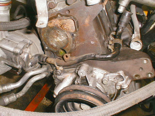
The
rubber elbow connecting the pop-off valve and the line to the manifold is crumbling from
20 years of heat and flexing. Replace it just because. To replace the elbow you must
either remove the turbo or the water pump and disconnect both ends of the pipe; as the
pipe is captured behind the water pump and oil pump and the turbo.
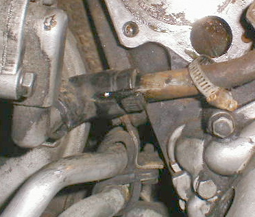
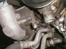
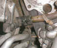 A
close up view of the cracked elbow. This was not evident until the engine had been
partially dismantled.
A
close up view of the cracked elbow. This was not evident until the engine had been
partially dismantled.
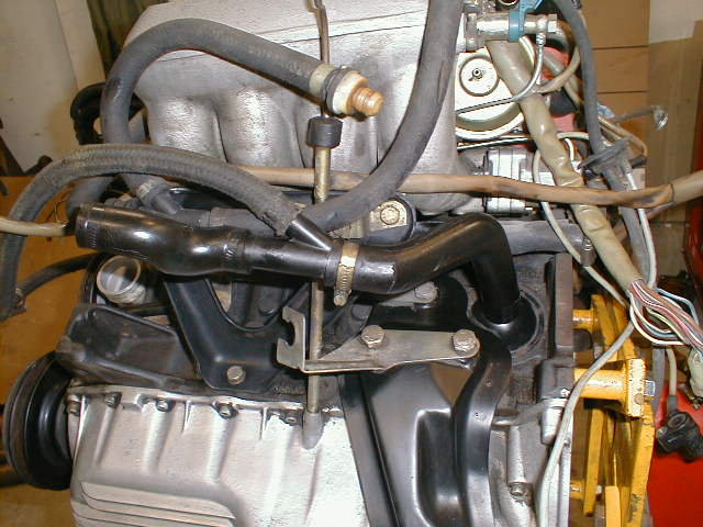
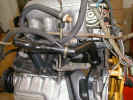 The
breather arrangement is unique to the 931. At left is an 82 showing the hoses coming from
the block. The 'y' goes to the oil return line from the turbo to the oil pan. The main
hose attaches to the air/oil separator.
The
breather arrangement is unique to the 931. At left is an 82 showing the hoses coming from
the block. The 'y' goes to the oil return line from the turbo to the oil pan. The main
hose attaches to the air/oil separator.
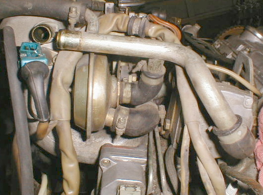
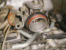
 A
rear view of an 82 931. In the middle is the deceleration valve. At the right is part of
the air by-pass valve. Part of the fuel control pressure regulator is bottom middle.
Follow the pipe from bottom right diagonaly up and left to the (missing) elbow fitting
above the cold start injector. To the left of the cold start injector the small line is
for manifold pressure to the control box in the 'cabin'. Note that the deceleration valve
is essentially in parallel with the air by-pass valve. They both 'bleed' some air around
the throttle butterfly at different times and for different reasons.
A
rear view of an 82 931. In the middle is the deceleration valve. At the right is part of
the air by-pass valve. Part of the fuel control pressure regulator is bottom middle.
Follow the pipe from bottom right diagonaly up and left to the (missing) elbow fitting
above the cold start injector. To the left of the cold start injector the small line is
for manifold pressure to the control box in the 'cabin'. Note that the deceleration valve
is essentially in parallel with the air by-pass valve. They both 'bleed' some air around
the throttle butterfly at different times and for different reasons.
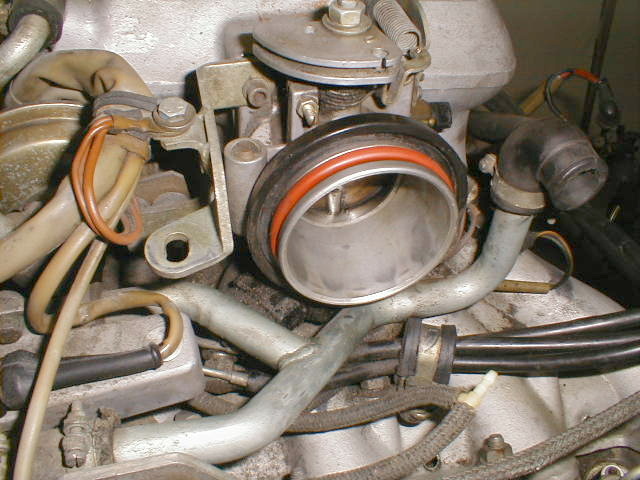
 Compare
the 81/82 throttle body at left with the 80 throttle body at right.
Compare
the 81/82 throttle body at left with the 80 throttle body at right.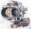 The 80 is almost identical to a 924 na part. It is connected to the intake pipe by a flex
hose coupling and clamps; prone to leak. The 81/82 uses a large O-ring (red). The black
ring only discourages dirt from working into the fitting. The 80 has two electrical
switches on the bottom. The later unit replaces those with a monoblock type switch just
barely visible below and left of the throttle opening.
The 80 is almost identical to a 924 na part. It is connected to the intake pipe by a flex
hose coupling and clamps; prone to leak. The 81/82 uses a large O-ring (red). The black
ring only discourages dirt from working into the fitting. The 80 has two electrical
switches on the bottom. The later unit replaces those with a monoblock type switch just
barely visible below and left of the throttle opening.
Peter Utzon shared this tech suggestion:
Looking for a cheap safe way to get some more power from your 931? The Saab APC turbo
boost pressure control system is easily scavenged from a wrecking yard and modified for
use on a 931. This site contains comprehensive information that will help people
interested in adding this state of the art system to their car. http://www.teleport.com/~bertram/volvoapc/
There's another good website with some interesting tips about how to add and modify
turbos on VW's, which as we all know are basically the same as our motors: http://www.geocities.com/turbogti2000/tech/tech.html.
They talk about advanced techniques such as water/alcohol injection, addition of
intercoolers, CIS mods, etc.
Cut the "J"pipe to the wastegate and weld a slip sleeve over the center of
the pipe to allow for expansion and twist. Most J pipes will break at either or both
ends and can be welded once at each point. The OEM piece is not welded but swaged into
the steel flangeplate. Make sure the wastegate braket is aligned and torqued correctly.
The studs in the head MUST BE stainless as do the mechanical locking nuts. The thermal
expansion is such that the ordinary studs/nuts will also work out. The nuts for the
bottom of #3 exhaust port are very hard to reach. JPasha
First; there is a strong school of thought that the 931 turbo is not
the weak link and will easily produce all the power you or I could ever use.
(Remember?" ... does not respond particularly well to bolt ons.") So you might
first want to optimize the turbo installation and the rest of the engine. If you have an
early car update to the later intake runners and throttle body. Use the late digital
ignition (not trivial however cause you must then change out the flywheel). And of
course, make sure your turbo is up to snuff. We are suggesting that it is adequate in
stock form. But not in its probable old abused worn out form.
So have it rebuilt. Check out the links and shops here and elsewhere. Let us know
your discoveries and we will share them here.
At Hershey this year we discovered another 924 aficionado who is 'in the business'
with expertise. K-W Collision Center, Waterloo, Ontario, Canada, (519) 888-7711.
Operated by Edmond Colicos. Ed had his 80 931 down at Hershey where we found him
scrounging for turbo cores and other goodies. Try talking to Ed about rebuilt turbos,
custom inter-coolers, used ignition parts, you name it.
Raising boost on the 931 can be done in a number of ways. One option, rather than the
more common approach of bleeding pressure off of the wastegate sensing line, is to
replace the spring within the wastegate. Since the wastegate is, for all intents and
purposes, a 930 wastegate, parts are interchangeable. Andiahl, long a name in Porsche
performance and racing circles, sells a 1.0Bar wastegate spring (stock 931 boost is
0.80Bar). They also sell replacement wastegate diaphragms, as well as stronger ones for
racing. They can be found at www.andiahl.com. Of
course, it's possible to get the spring for less from AJ-USA.
 One
excellent reference book on the subject of turbo modifications and upgrades is Maximum
Boost, by Corky Bell (Bentley Publishing,
ISBN 0-8376-0160-6). It gives excellent information on both the theory and practical
execution of designing new turbo systems or modifying factory turbo systems. It is a
very good read, can be understood without an engineering degree, and is highly
recommended before attempting any serious modification to your turbo system.
One
excellent reference book on the subject of turbo modifications and upgrades is Maximum
Boost, by Corky Bell (Bentley Publishing,
ISBN 0-8376-0160-6). It gives excellent information on both the theory and practical
execution of designing new turbo systems or modifying factory turbo systems. It is a
very good read, can be understood without an engineering degree, and is highly
recommended before attempting any serious modification to your turbo system.
David Ewings Turbo Mods
The problem with the turbocharger in 924 Turbo is the flange (3 hole vs. the usual 4)
and the size, both of which make for vendors saying there are no performance
options. The turbo must be larger to flow more air and at the same time not
introduce excessive turbo lag. I have been trying to get a trick turbo for this
car since November 1998. Auto Atlanta will provide a turbo for $1,200.00;
that is way over my budget. Majestic Turbo in Florida has developed a
procedure which will use the KKK 26 core (ed note: the stock unit) and rebuild it with
Garrett T-3 components. The cost, $800.00 a lot of money yes, but bolt in and
completely compatible with the existing oil lines and manifold. The turbo output
flange is different, therefore the plumbing will require some modification.
Kiwi Wind-up Boost Modification
Check out this Excel file with details on how to wind up
the boost by modifying the wastegate plumbing on your 931, from John Heaney in NZ.
Again, in case you missed it above, there's another good website with some
interesting tips about how to add and modify turbos on VW's, which as we all know are
basically the same as our motors: http://www.geocities.com/turbogti2000/tech/tech.html.
They talk about advanced techniques such as water/alcohol injection, addition of
intercoolers, CIS mods, etc.
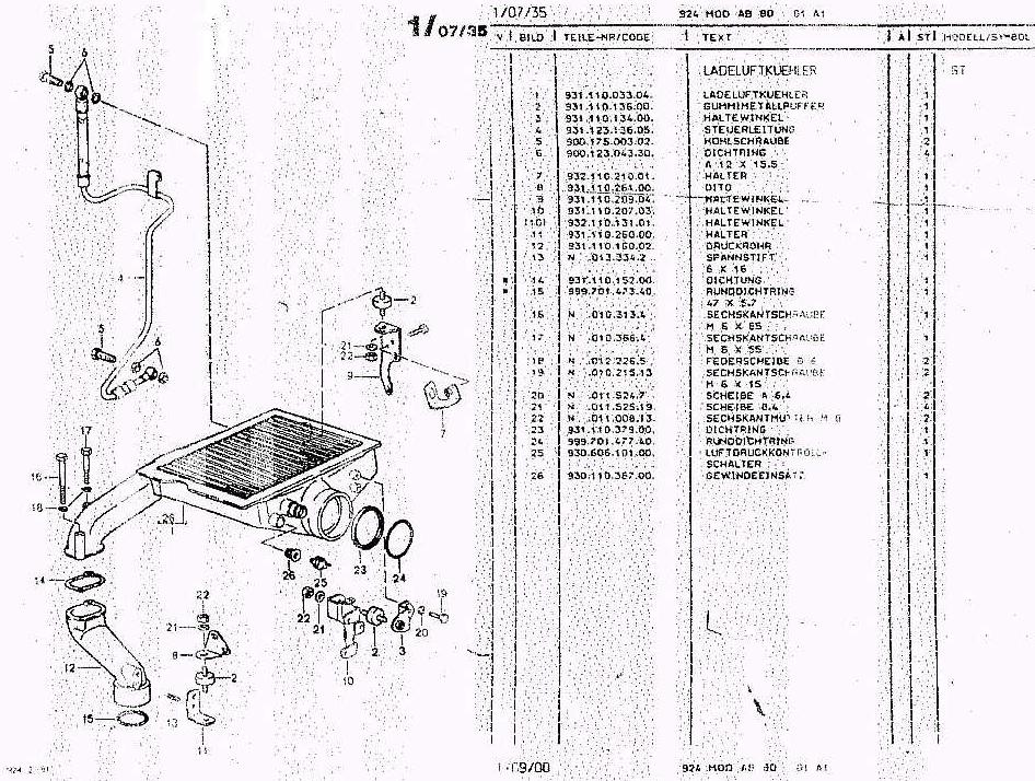
The 924 Carrera GT used an
intercooler located above the valve cover to minimize the increase in intake plumbing
volume, in an attempt to reduce any addition of lag created by adding the intercooler
over the stock 931 turbo plumbing. However this is a rather poor location for a heat
exchanger, being aligned with the overall air flow direction (rather than perpendicular,
or even at a modest angle, as any good heat exchanger should be). This resulted in the
necessary hood scoop that looks so macho on the hood of the Carrera GT. The NACA duct on
the hood of the stock 931 is strictly to allow additional air into the underhood area,
specifically in the area of the exhaust manifold, turbo, and wastegate, in an attempt to
keep ambient temps down. I'm not sure that this was the best location for such plumbing,
however, based on what I've read and observed about underhood aerodynamics. Furthermore,
while this layout did achieve its goal of minimizing the addition of lag to the system,
the intercooler is rather small in size by today's standards. The Carrera GTS, with a
much higher output, used an intercooler that, while unique to that car, was very similar
to the 951 (944 Turbo)'s intercooler. This can be mounted behind the bumper, as detailed
below by Michael Varholy, or in much the same location as the 951 by lowering the
radiator to allow the hoses to pass above the radiator. - Vaughan Scott
Many owners have thought of installing an intercooler
in their vehicle .Some have searched for the original Carrera GT unit. Some have tried
the 951 unit, and some have fitted units from other makes. No luck trying to find an
original. The only one that could be located was priced at $2500/US. There are also �homemade�
units available ,but the quality may be questionable, so those were avoided. A 951 unit
was purchased at last year�s Hershey swap meet for $150/US. The unit�s part number
is: 951.110.137.03 It is very large and well constructed. It was used on the 951 Turbo
S, which produced 247hp: a 931 won�t outgrow it!
The port sizes are a close match to the 931 plumbing.
Mounting and connecting the unit can prove difficult. Up under the bumper seems to be
the only place; this will put it right in front of the radiator/condenser. Overheating
is already a problem for many 931�s, so cooling system improvements are usually
required: a larger radiator, cold thermostat and larger fans will help. Additionally,
there is an aftermarket fan switch available that will turn the fans on sooner and keep
them running longer. This will keep temps considerably lower.
The unit already has two mounting holes in it at each end. Four holes were drilled
though the bumper and M10/1.5mm bolts secured the unit. A screen was used to
protect the unit from flying road debris.
Plumbing was the most difficult part of the installation. The enormous washer fluid
tank was removed and a smaller one connected elsewhere. Next, the headlamp motor,
linkage, and buckets were removed and GTS clear headlamp lenses installed. This
eliminates contact between the new piping and the headlamp hinge. A large open space is
then available to run piping to the top of the turbo. The connection for the other end
was very difficult and involved relocating the air filter and coolant tank. This
was done in order to keep the piping as short as possible, thereby minimizing turbo lag.
There are other less complex ways to make the connection with longer piping, but
it can be a tight fit.
The control line for the waste gate and other hoses must be connected to the new
piping. The boost limiting switch must also be relocated. On this car the switch was
eliminated and, in its place, a one bar mechanical relief valve was installed. This will
relieve overboost, in the event of waste gate failure, without cutting off the engine.
This valve was installed as a personal preference and is not needed. Ignition advance
and fuel mixture, as well as other adjustments, may be needed. Several types of piping
can be used; copper pipe and truck radiator hose work well together.
This unit was installed on an 1980 931 M471 with Audi 5000
throttle body, medium cam, larger air box, and numerous other modifications. Horsepower
increased significantly, particularly at higher rpm�s. Slightly more lag is also
evident. Fuel mileage is slightly higher than previous. A larger front valance will
improve appearances, as the unit protrudes slightly at the front. The turbo appears to
run cooler, but it will begin to glow if the engine is operated continuously above
7000rpms. Results will vary with installation and usage.
This text was written by Daniel J. Varholy. Any ideas, comments, or
problems can be sent to:
DVARHOLY@AOL.COM
Good Luck!
Pop-off Valve, Removal and Installation, Bob Dodd, bcdodd@rapfire.net
The noise is gone. The Pop-off valve was causing it. I
wouldn't say it was a must fix item. But it does indicate the need for
maintenance. The fit between the piston and the spring on one end and the guide
sleeve and spring on the other end was too large. I believe it was causing the
spring to rattle at low rpms. Here is the remedy and the process to remove and reinstall
the unit in a timely manner while the
motor is together. The gaskets are 930 items. I don't have the part number
but I will post it later when I get my replacement set in. I used some spares that
had lost their part bag years ago.
1. On a cool motor use brake clean or your favorite cleaner to remove any oil/dirt
from the compressor housing and end plates. One thing to note is that this is an
oil leak prone area so you might want to hit it first with a pressure washer using
soap and then a solvent to remove any hard deposits. In my case the seal on
the end plates along with seeping oil cooler lines had made the area a mess.
2. Start with the end plate closest to the frame. Loosen and remove (if
possible) the top two 10mm bolts, then loosen and remove the bottom two in succession
allowing the plate to be pushed by the spring. NOTE: one or more of the bolts may not
come out of the housing because of clearance, remember those bolt positions when the
time comes to reassemble. You can use screwdriver handle between the plate and the frame
to hold the plate in place to allow easier removal of the last two bolts.
3. You should be able to slide the plate out, and letting the piston push itself against
the frame. The piston may want to bind, just work till it gets to the frame.
4. Now the other plate, this is the hard side. Loosen the hose clamp on the
rubber elbow. You might think about loosening the clamp holding the lines to which
this rubber elbow attaches. Just in case you need some room to flex the elbow
around.
5. Start with the hardest to reach bolt. This is the one behind the pipe
which the elbow attaches to. It is a slow process with a box end wrench. I
wouldn't recommend using the open end till you get the bolt broke loose. I
happened to have dog bone wrench from Mac which has a swivel socket on one end and a
open end on the other. It made the job
lots easier. But like I said it is just a slow process but it will
slowly come out. You might try your fingers to turn it. Mine where a little
to large to get to the bolt. Next bolt is the one on that same side behind the
housing. These two need to come out first.
6. Once you get those two out proceed with the last two which are easier to
access. I would take the harder of the two out first. The spring pressure
isn't as great and the plate won't bind near as much since the other side is gone.
So you can leave one bolt in till the last. Once you get the last one out you will
see that the hose is kinda of holding the plate in place. Slowly work the plate
from the elbow. Be careful to not break the elbow. They are expensive and
difficult to replace in this location.
7. Once this plate is out you will see the spring and the guide
sleeve. Pull it out, remembering the piston on the other side has a chance
of falling so be prepared to catch it.
8. You got it out. Now just clean everything. Inspect
for wear. Remove the old gasket material. Clean the bolt holes on the plates.
Clean the threads on the eight bolts (this makes install easier). Clean the gasket
surface on the compressor housing. Spray some brake clean in the bolt holes to
remove any oil and dirt from the threads.
9. Now comes the time to check the fit of the spring to the other
parts. What I did was first measure the length of the spring. I had a spare
unit and it measured 6.375 in length. The unit I was working on was about
.375 shorter than the other, so I carefully stretched it past the length so it would
settle to 6.375 or close. I then used a small weight and checked the deflection of
the both springs as a comparison.
They both deflected the same amount at the same length before and retained length after
the weight was applied. This told me I was in the ball park. I then checked
the fit of the spring inside the piston, I carefully bent the last link outward to
fir snugly inside the piston. You can turn the piston down with spring inside and the
spring stays put. I did the same procedure with the sleeve, but this time
carefully bending the link inward. This made a tight fit. By the way I used
two pairs of pliers, one was a needle nose vise grip and the other just normal
blunt needle nose pliers. Be careful not to bend or mare the spring where the
pliers make contact. If you do just sand it till you remove any burrs. NOTE:
You want to try and not cause any damage on the spring that can develop a stress
crack. I checked the spring for length after this and it held.
10. Your unit may or may not have a spacer washer between the
spring and the sleeve. I feel it was added to allow the spring to sit flat on the
sleeve. If you have, you will note a chamfer on one side, on the ID (inside
diameter), this is the side that sit against the sleeve. The sleeve has a radius
on the shoulder where the spring sits and this spacer makes up for that radius.
11. Well you should be set to reinstall. The reinstall is
different slightly. Leaving the piston out, install the spring with the guide
sleeve. On the side where the frame rail is take a steel rule or 1/8 to 1/4 thick
1 inch wide metal plate long enough to span from one side of the piston bore to the
other. And slip the bar through the spring to the center of the bore, rotate the
spring in the direction needed to draw the spring into the bore till it is
flush with housing on the other side. This is going to let you install the
end plate on the hose without any tension from the spring. Install your plate and
gasket, connecting the hose, installing the bolts in sequence from hardest to
easiest. Tighten those clamps on the hose and the lines and that side is
done. NOTE: is takes a little patience to get everything in , be careful you
get the gasket installed correctly. It can help to apply some assembly lube to the
gasket to help it stay in place even though the housing is built in way to help hold the
gasket.
12. Now take the bar out and get the piston ready. You
shouldn't need any lube and it can get in the way when trying to get this side
assembled. The turbo will eventually seep enough oil to lube the piston.
Take that same bar and compress the spring to allow you slip the piston in between the
frame and housing. IT take a little patience and care but you can manipulate into
place without prying, remember we don't want to kink the spring. Once you get the
piston in , use your fingers to push it in and slide the plate with gasket on top of the
piston. NOTE Don't forget the bolts that didn't have room earlier , you will need
to add them to the plate at this time. You can always let the whole
thing spring out against the frame to align it or to take a breather. Use
your screwdriver handle as a pry bar/install spacer block ( I didn't want to scratch
anything is why I used the handle) and install the easiest bolt till it has gripped
enough threads to hold the plate where you can thread the other bolts into place.
The piston should be in the bore and the gasket centered and held into place by the
housing. Tighten away.
13. Look over everything, making sure you didn't forget to torque a bolt or
tighten a clamp. That is it. No more noise ( at least from that part of the
motor), no more vacuum leaks, nor more oil seeping. My popoff valve made a nice
soft clunk during operation, so I know it is working. I did notice that the car
had more of a defined boost noise, maybe my imagination. I estimate it took about
five hours to R&R the item, from cleaning the area to the final reassemble.
The aggravation is the small tight confined area and dirt. So jack the car up as
high as you can and get a good light to see by. And give it a good cleaning, you
don't want to have anything drop into the turbo intake side and go into the motor.
The throttle body from the 82 turbo is virtually identical to that of a
944 (standard), Darryl Snover.
Regarding the recent discussion about boost pressure.
The Euro versions have
7.5:1 compression and 0.7 bar boost,
8.5:1 compression and 0.65 bar boost
8.5:1 compression and 0.75 bar boost with GT intercooler.
As the US versions have 7.5:1 and 8:1 compression, I think that it will always
be safe to go to 0.7 bar boost.
Fitting a variable boost controller is especially easy on the US models, as they
run with 0.45 boost. You just fit one hose to the top of the wastegate, by
removing the small black filter, and the other hose somewhere on the inlet
manifold. I fitted mine at the hose to the ignition computer by using a longer
banjo bolt.
I have a modified engine with 8.5:1 compression and a large intercooler, and the
recommendation from the manufacturer was to increase the boost to 0.8 bar
without modifications, or to 0.9 bar with retarded ignition. (Done by fitting a
pressure sensor with a switch that breaks at 0.8 bar, to the octane loop).
Yours,
Ole Kammersgaard
mailto:Ole.Kammersgaard@mas-int.com
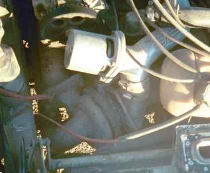
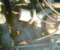
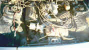 Carlos
Nunez has an aftermarket turbo installed in his 77
924. You can see this installation has the turbo in front of the engine.
Carlos
Nunez has an aftermarket turbo installed in his 77
924. You can see this installation has the turbo in front of the engine.
Possible mods?
Hello from the abyss. I have been doing some research on turbos, and have found that
the 84-87 Buick Regal Turbo's and Grand Nationals also have a 3 bolt exhaust flange, and
that the 86-87 intercoolers seem to be a nice unit. Check out http://www.gnttype.org
to see the specs. These cars produced any where from 200-400 HP with the stock turbos.
They are rated at 0-20 PSI and have an integrated waste gate. Just My Two Cents.
Jim Rogers
Re: 931 waste gate diaphrams
From: Bobby
Email: porschetech@mac.com
Call ANDIAL in CA and they have 930 diaphragms which is what is used in the 931 wastegate.
They offer two types one stock (60$) and the other teflon for racing ($80), the cost is an
estimate from memory. Also ask about the springs and shims. You can opt to add a one bar
boost spring at this rebuild time if you want to boost the car like a rocket. I did a 81
of mine and had no ill effect so far.
 The
rubber elbow connecting the pop-off valve and the line to the manifold is crumbling from
20 years of heat and flexing. Replace it just because. To replace the elbow you must
either remove the turbo or the water pump and disconnect both ends of the pipe; as the
pipe is captured behind the water pump and oil pump and the turbo.
The
rubber elbow connecting the pop-off valve and the line to the manifold is crumbling from
20 years of heat and flexing. Replace it just because. To replace the elbow you must
either remove the turbo or the water pump and disconnect both ends of the pipe; as the
pipe is captured behind the water pump and oil pump and the turbo.